Featured Article

Tuesday 26 November 2013

Cisco 2500 Series Password Reset

Real World Application:

2500 series router already alarming see in production environments, there are some, however, for over 8 years today and production or more. Cisco 2,500 series routers are the most common use is for training purposes only; commonly used in a lab environment, make great introductory router 2500 series router Cisco IOS (internetwork operating system).

Lab Prerequisites:

A Cisco 2500 Series router that has an unknown console or enable password.
An active Serial Console session to the device that you’re unable to login to.

Lab Instruction:

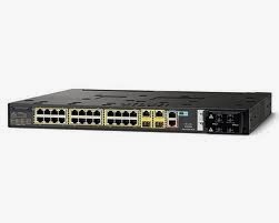
Like this is Cisco 2,501 router, there is a console password on the device. Use this password, you cannot access the exec mode and not properly authenticating the password. Use when buying a router, you may often have such programmes.

Router con0 is now available

Press RETURN to get started.

User Access Verification

Password:

Step 1 . Power cycle the router or power on the router first. When the router is started, you need to break into network cards PXE boot ROM to boot the router boot sequence, by holding down the CTRL key and press pause break like you. Repeat this operation until you put the network adapter PXE boot ROM prompt.

System Bootstrap, Version 11.0(10c), SOFTWARE
Copyright (c) 1986-1996 by cisco Systems
2500 processor with 14336 Kbytes of main memory

Abort at 0x10B1F3C (PC)
>

Step 2 . When you change the configuration register boot to Cisco IOS router will ignore the contents of the NVRAM. To set the configuration register to 0x2142 and initialize a router (boot to the IOS router).

>o/r 0x2142
>i

Step 4 . (Option 1)-to a Cisco IOS router starts, initial configuration of the system dialog box prompts you, type n and press enter here and you will be placed in user mode. Now you can put your self into privileged mode, enabled by typing. Once in privileged mode, you can copy the startup configuration to the running configuration, and then manually change the password and then save the configuration to NVRAM by typing copy run start.

Step 5 . (Option 2) – to the Cisco IOS router starts, initial system configuration dialog box, you are prompted to, type n and press enter and you will be placed in the user mode. Now you can put your self into privileged mode, enabled by typing. Once in privileged mode, you can clear the contents of the NVRAM by issuing the write erase command.

Router#configure terminal
Router(config)#config-register 0x2102
Router(config)#end

Configuring a GNS3 Ethernet NIO Cloud

Real World Application:

In this lab, you will learn how to find free configurations in the lab of NIO using GNS3 CCNA Binder Ethernet (network input/output).

GNS3 if you are using, and then free CCNA Binder, you will need to connect to the router using your host. Windows XP Professional running on a PC at the same time, can create a binder with GNS3. Although it is possible for other operating systems (such as Windows Vista or Windows 7 running on GNS3, GNS3 compatibility, it is currently recommended for Windows XP on a computer that is running the GNS3.

This lab will show you how to configure an IP connected to the Ethernet interface of the local host for Cisco GNS3 Microsoft loopback interfaces within the device. This simulates a physical connection to the Cisco simulation platform.

You can choose to bind the GNS3 cloud your physical adapter instead of the Microsoft Loopback adaptor; when you use that lets you choose from within your local network you want to connect another device to the GNS3, Cisco device physical adaptors, but connected to GNS3, Cisco devices via the local hosts crash Dynamips Engine possibilities are very high.

Please note that you may have compatibility issues with Windows 7 and Windows Vista 64 bit the loopback interface, it is recommended that a 32-bit operating system.

Lab Objectives:

On Windows XP, install the MS loopback interface
In the newly created the MS Loopback adapter is configured on an IP address.
Creating a cloud in GNS3 interface and bind it to a newly created the MS Loopback adapter.
By assigning an IP address to the same subnet, you assign SW1 MS Loopback adapter to verify your connection. For demonstration purposes laboratory, Binder CCNA devices will use 192.168.255.1-8/24 for free and host is 192.168.255.10/24
  • On Windows XP, install the MS loopback interface
  • In the newly created the MS Loopback adapter is configured on an IP address.
  • Creating a cloud in GNS3 interface and bind it to a newly created the MS Loopback adapter.
  • By assigning an IP address to the same subnet, you assign SW1 MS Loopback adapter to verify your connection. For demonstration purposes laboratory, Binder CCNA devices will use 192.168.255.1-8/24 for free and host is 192.168.255.10/24
Lab Instruction:

Step 1 .Navigate to control panel, click Start > or by loading my computer and control panel in the left column "other location", click Control Panel


In Control Panel, double-click "Add Hardware" icon and the Add Hardware Wizard will pop up as shown;


After you click Next, the wizard will automatically search for new hardware; it may take a few minutes;


New Hardware Wizard finished searching and not found, you will be required after the new hardware is connected or not, the bullet is connected hardware, click Next


Sliding to the bottom right of the list to scroll and highlight add a new hardware device, as shown in the following and click Next;


Now, you will not be prompted or you do not want to add new hardware wizard to automatically search for new hardware. Click bullets at the bottom say installing I manually select from a list (Advanced), like this hardware, click Next;


Now give you a different type of list, you can choose to install the hardware. Scroll down the list and select the network adapter as shown below and click Next;


The next window will be displayed on the left hand side and can be used to install manufacturing equipment list on the right side. Some computers may have multiple manufacturing options, if so then select Microsoft made in the list on the left, and then select Microsoft Loopback adapter on the right side of the list, as shown in the following options, and then click Next;


You display the hardware you are trying to install it, as shown below, just click Next and Windows will install the equipment installed before. May pop up a window with a progress bar shows the progress of the installation of device drivers;


Once the Microsoft Loopback Adapter is installed click finish as shown below and restart your computer;


Configuring the Free CCNA Workbook GNS3 Topology

Real World Application:

This lab will teach you how to import free loose-leaf book CCNA Labs GNS3 topology. This is required if you don't set up a physics laboratory for the use of this Web site.


Real-world application but does not apply to this lab in this lab, you will learn how to configure free CCNA Binder GNS3 topology 95% all free CCNA lab found in binder used.

Lab Prerequisites:

Installation of GNS3 and GNS3 environment variable configuration, including the working directory, execution paths, TEMP and IOS image directory path. If you do not have this completed check the basic graphical Network Simulator Lab 1-5-1-6--v3 configuration install a graphical Network Simulator v3
Extraction and c3725 and has in previous laboratory image c3640 platform locations are listed in the Cisco IOS image.

Ensure that importing loose-leaf book free CCNA lab topologies in the stub zone before networking configurations in GNS3 topology and 3,725 platform or the import will fail.

Lab Objectives:

Loose-leaf book downloads and free CCNA lab topology file import.
Successfully started in the lab topology of all routers and the idle PC values for each device.

Familiarize yourself with free CCNA Binder topology view GNS3 topology or by visiting the topology page found in the main navigation bar at the top of the page.

Lab Instruction:


Step 1 . First off you need to make sure that you download the free CCNA Binder GNS3 topology file by clicking the link on the left hand side bar, or by clicking here!

Step 2 . You download a free CCNA Binder after GNS3 topology file, unzip it to your desktop or you save documents to a folder.

Step 3 . By double-clicking on the file load the GNS3 topology, GNS3 should automatically load, and import topology.

Step 4 . GNS3 load and topology after you import, you can then start with R1, right-click, and then click on the start menu. Once you start the device, you can right-click the device and click the console again PuTTY terminal emulation window appears. This will provide you with a console access topology R1.

Upon confirmation, the led on the router to user mode if the system prompts you to type the letter "n" to skip the initial configuration dialog box and wait until you receive a prompt routers >

After you have received a user-mode prompt, you will need to wait about 10 seconds, until the router is idling, then you need to configure the router, with its own idle PC values. Running Dynamips Dynamips is a very processor-intensive applications, and within each of these devices will require an idle PC values, can be applied to the device, therefore, the application can reduce the physical processor load. Please note that an idle PC values are required for each device.

Experiment with your idle PC values, these values are different on a per-machine basis. Be sure to watch your processor utilization when idle PC values to determine which will work best for your machine tested. You can start the Task Manager, when your task bar; click here to view your current processor utilization, then click Properties.

Once success has started all of the devices in the topology, and apply to each device's idle PC values, you should familiarize yourself with the binder CCNA free topology. By clicking the topology of links in the top navigation bar or click here, and you can do it!

Basic GNS3 Configuration

Real World Application:

In this lab you will learn how to configure GNS3 CCNA Cisco equipment for training purposes of the loose-leaf book of basic parameters.


Actually illegal to use in the "production environment" PE se GNS3, it can, but is a great tool for the configuration verification (s) and training. In this binder is to all intents and purposes, you will be using GNS3 and fundamental in learning the ins and outs of Cisco router and switch configuration.

Lab Objectives:

In this lab, you will learn how to configure GNS3 CCNA Cisco equipment for training purposes of the basic parameters of the loose-leaf book.


Actually illegal to use in the "production environment" PE se GNS3, it can, but a great tool to configure verification (s) and training. The programming sequence is to all intents and purposes, you will be using GNS3 and learn the ins and outs of Cisco router and switch configuration.

If you wish to use other images, you will have to manually configure them in the GNSv3 topology.

Lab Instruction:

Step 1. First launch the GNS3 application for the first time and you’ll be prompted by the GNS3 Setup Wizard as shown below;


Step 2 . You need to configure and test the paths and Dynamips (router emulator engine) you can click on the button, the installation wizard prompts, you will be prompted with the following configuration window figure 1 into the working directory. Verify that the path information is correct. But if you want to use SecureCRT on Windows x64, then you will need to change the command string for the Terminal application c:\PROGRA~1\VANDYK~1\SecureCRT\SecureCRT.exe "Terminal settings" tab in GNS3 setup packages include PuTTY/T/N%d/telnet 127.0.0.1%p


Step 3 . Dynamips listed down the left hand side of the Preferences window click on the tab and verify that the path to the executable file and the working directory is correct. Once you are done, click the test button, if all configuration variables are the best button for service you can receive messages, reading; Dynamips started successfully


Loose-leaf book free CCNA Cisco GNS3 topology used and 3,725 router. Before you continue, get the images listed in the prerequisites and open using WinRAR and extract the image to \gns3\images\ to extract images

Step 4 . Can Dynamips started successfully, return to the installation of GNS3 Elves out of GNS3 preferences window. Now, the business variables are correctly configured, you will need to configure your router to use baseline configurations in GNS3. In GNS3 number 2 box, click the installation wizard to launch the IOS image and hypervisor configuration window. You need at least 128 MB RAM configuration and 3,725 platform and platform to point to the correct image is uncompressed, you are placed in \gns3\images\


Please note that the latest free CCNA Binder GNS3 topology needs, change the memory usage of hyper-visor is limited to 2048, you can by clicking on the hyper-visor Organizer tabs when you Dynamips configurations in GNS3 Preferences tab.

Step 5 . Once configured by the two platforms required stub local area network topology (shown below) you can sign out IOS and Super visor GNS3 configuration window and exit the installation wizard, and you are ready to continue to the next lab, will need to import the stub zone networking GNS3 topology configurations.


Configuring a Cisco Access Server

Real World Application:

This lab will teach you how to configure a Cisco access server, can be used to access all of your Cisco lab equipment from a single point of administration.


Often times, companies will use for network access server in a rack of Cisco equipment direct console access, which will allow remote administrators overloaded router and scheduling, and booting into ROM monitor mode check the boot configuration of a remote password recovery, image recovery, and access control lists.

Lab Prerequisites:

  • Complete Lab 1.2 before attempting this laboratory or opens the current Cisco access server console session.
  • Make sure that the access server asynchronous wires to the venerable device. Example;
Lab Objectives:

  • For your preferences, access to the server is assigned a host name.
  • Loopback interface is configured to use a reverse Telnet session.
  • Correct row inserted into their respective devices configured on the local reverse Telnet to the loopback interface IP hosts. See, for example, the lab prerequisites.
  • Prevent asynchronous lines with access to an EXEC session to the server.
  • Transport entered in asynchronous online configuring Telnet Protocol.
  • Optional – to prevent reverse Telnet session timeout on asynchronous lines.
Lab Instruction:

Step 1 : Assign a Hostname to the Access Server of your preference.

Router>enable
Router#configure terminal

Enter configuration commands, one per   line.  End with CNTL/Z

Router(config)#hostname Access_Server
Access_Server(config)#

Step 2 : Configure a loopback interface for use in reverse telnet sessions.

Access_Server(config)#interface loopback 0
Access_Server(config-if)#ip address 10.10.10.10 255.255.255.255
Access_Server(config-if)#exit
Access_Server(config)#

Step 3 : Configure the local host IP, loopback0 interface and reverse Telnet dear asynchronous line. To view the available line of digital distribution for your platform on the show line command from global configuration.

Access_Server(config)#ip host r1 2001 10.10.10.10
Access_Server(config)#ip host r2 2002 10.10.10.10
Access_Server(config)#ip host r3 2003 10.10.10.10
Access_Server(config)#ip host r4 2004 10.10.10.10
Access_Server(config)#ip host r5 2005 10.10.10.10
Access_Server(config)#ip host r6 2006 10.10.10.10
Access_Server(config)#ip host sw1 2007 10.10.10.10
Access_Server(config)#ip host sw2 2008 10.10.10.10
Access_Server(config)#ip host sw3 2009 10.10.10.10

Step 4 : Prohibit the async lines from establishing an EXEC session with the access server.

Access_Server(config)#line 1 16
Access_Server(config-line)#no exec

Step 5 : Configure the transport input protocol on the async lines to Telnet.

Access_Server(config-line)#transport input telnet

Step 6 : Optional – Prevent reverse telnet sessions on the Async lines from timing-out.

Access_Server(config-line)#exec-timeout 0 0
Access_Server(config-line)#end
Access_Server#

To exit this session use the key stroke combination Ctrl + Shift + 6 then X Executing this key stroke combination will take you back to your Access Servers CLI.

Access Server#r1

Trying r1 (10.10.10.10, 2001)... Open

% Please answer 'yes' or 'no'.

Would you like to enter the initial configuration dialog? [yes/no]:

Access Server#

You will have several commands available for troubleshooting and Diagnostics. As shown in the show hosts command is as follows;

Access_Server#show host
Default domain is not set
Name/address lookup uses domain service

Codes: UN - unknown, EX - expired, OK - OK,   ?? - revalidate
            temp - temporary, perm - permanent
            NA - Not Applicable None - Not defined

Host                    Port       Flags          Age  Type   Address(es)

r1                      2001       (perm, OK)    0        IP      10.10.10.10
r2                      2002       (perm, OK)    0        IP      10.10.10.10
r3                      2003       (perm, OK)    0        IP      10.10.10.10
r4                      2004       (perm, OK)    0        IP      10.10.10.10
r5                      2005       (perm, OK)    0        IP      10.10.10.10
sw1                     2006     (perm, OK)    0        IP      10.10.10.10
sw1                     2007     (perm, OK)    0        IP      10.10.10.10
sw3                     2008     (perm, OK)    0        IP      10.10.10.10

Monday 25 November 2013

Installing Graphical Network Simulator v3

Real World Application:

GNS3, often used as a training tool for people interested in learning how to configure a Cisco device, or even those who seek to achieve Cisco Career certification. GNS3 for all levels of students ' on my way from the CCNA Cisco CCIE certification training.


GNS3 is a training tool, but in the real world, is to configure the verify command to verify that another major purpose. If you want to know how to set the feature you have, but do not have the router and cannot do it on the router, and then light the GNS3, you are free to configure until your fingers are blue.

Lab Prerequisites:

  • Stub Area Networking recommends that your PC has at least a Dual Core processor with 2GB of RAM to run the Stub Area GNS3 topology.
  • Stub Area Networking highly recommends that your PC have a Quad Core processor with 4GB of RAM.
  • Download the GNS3 (Graphical Network Simulator v3) from the link in the side bar or by clicking HERE


Lab Instruction:

Step 1 . GNS3 all the links you need to download from a package provided in the sidebar, or you can choose to run it by clicking here or download it to a folder, if you want to keep the executable.

Step 2 . After you download, Setup, and then run the Setup, it shows you the installation wizard (shown below). Please note that you will need administrative privileges to install GNS3&WINPCAP (GNS3)


Step 3. After you are presented with the Installation Wizard click next to continue. You are required to agree to and accept the License Agreement for GNS3, if you do not accept this agreement then you must have a physical lab to do the labs found on this website.


Step 4 . After accepting the license agreement will be submitted for your option, rename the default folder name from the GNS3 found on the start menu to whatever you like. If you want to change the name of the folder, and then type it in manually, or you can accept the default "GNS3 ″, and then click Next.

Step 5 . Now provides you with the GNS3 setup packages that are included in this list. WinPCAP is a data capture/analysis GNS3 setup of network monitoring library included with data reported. Dynamips is GNS3; actual GNS3 router Simulator software is a graphical user interface for Dynamips. PemuWrapper is a Cisco PIX hardware emulator that allows you to run PIX Firewall network for GNS3 PIX devices. Can put all these packages are checked, and click Next.


Step 6 . Location of your folder will now be displayed, the installer will install GNS3. In the default case, GNS3 is installed to C:\Program Files\GNS3 if you are running a 64-bit OS and GNS3 is installed to the C:\Program files (x 83) \GNS3

Step 7 . GNS3 Setup will automatically download WinPCAP, and prompts you to install it, as shown below; WinPCAP install ads on the screen, click Next.


Step 8 . Click next on the WinPCAP Installer Welcome Screen.


Step 9 . You must accept the License Agreement for WinPCAP to install the software.


Step 10 . After accepting the License Agreement for WinPCAP, the software will install, click finish afterwards;

Identifying Router Components and Accessories

The early 90 's, modular business network equipment of Cisco equipment on the new policy. In the past, and series router Cisco 2,500, excluding 2524 has fixed port configuration, serial over Ethernet, token ring, ISDN, and terminal line, in such a way that it imposed a limited network of investment protection and scalability of business networks.

Announcement and release of the Cisco 3,600 series routers in 1996, enterprise investment protection that they do not feel relief is by replacing the entire router when you upgrade WAN and LAN link aggregation. Companies can easily from WIC (WAN interface modules) to Exchange migration using ISDN lines to a T1 line, and the LAN ports to upgrade to 10/100Tx and from 10Base-t nm (network module) changes.

Cisco announced in March 1998, 2,600 series routers are Cisco systems, to provide security of engineered wire-speed delivery of new generation multiservice routers also provide voice, data, video and wireless services, the next milestone. However, Cisco 2,600 platforms lacking which upset some network engineers in the industry as a whole it is the PCMCIA Flash card slots in a feature of the Cisco series routers provide 3,600. Engineers familiar with the 3,600 platforms found in the disaster recovery process recovery profiles, as well as the IOS image is simple with PCMCIA Flash memory card changes.

Around the same time as Cisco announced 2,600 series including 3,725 and 3,745-series platform. These platforms is Cisco equipment major stepping stone in architecture, because of platforms introduced removable Compact Flash (CF) memory card used with digital viewfinder. Even today, equipment such as, 2,800 series ISR (integrated services router), ASA 5,500 series firewalls and countless other platforms have been designed to take advantage of Compact Flash card (CF). Speed of the CF card to prove several times faster than previous technologies, using Cisco equipment is more flexible.

In May 2002, Cisco introduced Cisco 2600XM series multi-service router system architecture contains several upgraded features, such as the current Motorola processor, integrated in the revised edition of the 125 MHZ SDRAM 16 MB of Flash memory and 48 MB, maximum Flash and 128 MB RAM support.

Later, version 12.2 (8R) network cards PXE boot ROM, physical 2600XM series multiservice routers supporting 256 MB RAM. However, when first introduced in 12.2 (8R) it only provides "future-ability" using 256 MB of RAM. However in the given Cisco IOS 2600XM that is still limited to 128 MB RAM, 256 MB RAM, and 12.2 (8R) NIC PXE boot ROM network cards are the benefits of starting chips will extract the Cisco IOS image to fail to get IOS kernel address space. Traditionally image becomes greater contraction of processor addressable memory space as images are extracted and loaded into memory after booting (different from the 2500 series, runs directly from Flash) 2600XM platform which gives a significant performance boot-2600XM on platforms. When upgrades are offered, using 256 MB of RAM 2600XM platform gives you additional 50-60 MB or so of extracting image processor addressable memory is not residing in the IOS. If you have 256 MB RAM to run 12.3T on the show memory command, you will see the process should have 128 MB of address space is available. After October 2004 release of IOS version capable of handling a full 256 MB RAM minus uncompressed images.

2600XM also publishes Cisco 2,691 router and it is the fastest platform in the 2600 series. Designed with higher throughput, scalability, and bearing in mind the versatility. Cisco series routers are Cisco 2,691 series router's brother. Side-by-side comparison, they looked very similar however performance and modular design, and the price difference.

1800, 2800, and 3,800 series routers support HWIC (high-speed WAN adapter card), WIC technology previously only supports 8Mbps aggregates each PCI bus supports 400Mbps aggregations (shared across all sockets).

Example; 2600XM series has two integrated WIC slot on the shared bus. 2600XM supports 8Mbps speed runs of individual WIC 2T port port/4Mbps, but due to the shared bus, you cannot use the other WIC slot. This restriction also applies to the NM -1FE2W, NM -1FE1R2W, NM and -2FE2W nm -2W network module.

2,800 series ISR routers (excluding 2801) has four HWIC slots supports 400Mbps aggregations (400Mbps all slots on each chassis) and one or more (enhanced network module) NME slot within the cross-platform shared 1.2Gbps all slots in the business, while its predecessor; network module can only cross-platform shared by all network module slot for up to 600mbps of speed.


Connecting to a Cisco Device via Console

So you take a brand new Cisco router or switch boxes, and very first, you must install it before its basic configuration. To configure a Cisco device basics you first have to device console.

If you take a brand new Cisco equipment factory-you will see it with a blue ribbon cable has a DB9 serial port, and another network RJ45 connectors at the other end. Don't be fooled, this is not the "next-generation" Ethernet cable or token ring, but Cisco console cable to the connection cable.

You use this cable to connect to his Cisco devices via the serial port, you can configure the device using the command line.

Because Cisco devices do not have a graphics adapter or the ability to use a mouse and keyboard, you must connect with this feature, so you can configure the device CLI through the console to another computer device.

In order to connect to the Cisco devices via the console will need to use a terminal emulator application.

Usually performs this task by using the HyperTerminal application can be Windows, but is included in the Windows XP Windows Vista, and updates may require that you manually download/install this application.

Most popular terminal emulator PuTTY, is completely free to download, you can click on the useful links in the footer menu found in the section "PuTTY terminal emulator" link.

Most popular paid artwork developed terminal emulator called SecureCRT. The application writing the lab is $99 per single-user license and support SSH/Telnet/serial and a group of normally no longer be using other protocols. SecureCRT however provide a very useful scripts and logging features and the ability to save sessions in different folders, so you can easily connect to an existing device later.

In many cases, in real life, you may need to connect to the Cisco devices via the console, you configure misconfiguring locking themselves out of their access control lists to make a mistake, or maybe you hang, the processor by performing processor-intensive debugging commands. However, as a network engineer, you need to know how to become a Cisco device console.

Lab Instruction:

While most of the terminal emulation software of different features that are available and/or agreement, any terminal emulation program to achieve the same goal. In this walk through, PuTTY will use, which is free (see summary of laboratory) connected to a Cisco device and establish the control panel to the Cisco command line interface session.

Step 1: Connect your Cisco console cable or terminal adapter to a Serial port on your computer.

Step 2: Connect the RJ45 end of the console cable to the “Console” port on your Cisco Lab Access Server (Cisco 2509, 2511 or a Cisco router with a NM-xxA/S Network Module) do not power on your router yet.

Step 3: When first running the Putty executable you will be presented with the Putty Configuration Window as shown below.


Step 4 : After the PuTTY configuration window appears, bullets from moving SSH to serial;

Note: COM1 serial communications is the default communication port for PuTTY; you may need to change your COM ports to match your console cables to the ports. Speed of the default baud rate is 9,600 PuTTY. 9,600 is 0x2102 (configuration registers are discussed in a later chapter) configuration of Cisco devices that are registered by default speed.


Step 5 : once you verify that the COM port speed and click "open", a new window will appear. This window terminal window. COM#--PuTTY terminal window appears, your power to the Cisco device. After booting device; assuming NVRAM is clear, you will be prompted to install the program configuration dialog box:

After Setup configuration dialog box appears, type "n" to no and press the Enter key. Then you will be prompted to press ENTER to start! Press Enter to the router after a user mode command line interface that looks like the following,


After you have reached this point you have completed the objectives of this lab. Proceed.

How to Configure RIP Routing Protocol with two Routers

How to use a simple topology configuration for GNS 3 check the connection between the host RIP routing protocol.


1th step: creating a topology like and do basic configuration to the router interface IP address, IP address and a default gateway for hosts and topologies are the same.


Configuring a Management VLAN Interface

Switch in the world, called switched virtual interface for the VLAN logical interface. Exchanger you will see when you are configuring a VLAN interface these interfaces. You have the ability, like a FastEthernet interfaces to configure these interfaces. Can assign a VLAN interface IP address, the bridge group, the interface description and service quality strategy.

Have a VLAN interface to the 2nd tier equipment's ability to communicate with other devices on the 3rd floor. Multilayer switching uses the VLAN interface on multi-layer routing in an Exchange. Basically, the switch is a-rod on his router, which in Lab 4 20 discussions. Multilayer switched networks, switches, such as Cisco and Cisco 3,550 3,560 uses the VLAN interface as the default gateway for the host PC and other machines of the network to communicate with other IP networks.

For example, Cisco, with 3,550 VLAN,VLAN 10 and VLAN 20. One is assigned to each VLAN interface IP address of 192.168.10.0/24 and 192.168.20.0/24. When up VLAN, VLAN 10 on PC required 20 PC, which uses a VLAN interface with a default gateway and Exchange routing datagrams through layer3, Layer2 and switches and switch data reported in the new VLAN.

Second layer only exchanger at any given time only a single active VLAN interface. Management VLAN interface this interface call. 2900XL,2950 layer two Cisco switches including Cisco and 2960.

In this lab, you will familiarize yourself with the VLAN interface configuration mode.

Lab Prerequisites:

  • Than load if you use GNS3 CCNA free Binder GNS3 topology than starting system R1 and SW1.
  • Building R1 and SW1 configuration console sessions respecting the hostname of the device (s).
  • For verification purposes you will need to be configured on R1 VTY line password and assign the 10.1.1.1/24 the IP address of the host to the R1 ′ s FastEthernet0/0 interface
Lab Objectives:

  • Creating and naming the VLAN number 10 management.
  • Create VLAN 10 interface and assign IP addresses to 10.1.1.10/24
  • SW1 FastEthernet0/1 interface is assigned to VLAN 10.
  • By using R1 to Telnet IP address in VLAN 10 on SW1 to verify the management VLAN configuration.
I read

Laboratory demonstrates the use of Cisco Catalyst switches, NM -16ESW not be used in GNS3.

You should be familiar with the commands required to complete the objectives of this lab from previous labs in the Free CCNA Workbook.

Step 1. Create the VLAN number 10 and name it Management.

SW1 con0 is now available

Press RETURN to get started.

SW1>enable
SW1>configure terminal
Enter configuration commands, one per line.  End with CNTL/Z.
SW1(config)#vlan 10
SW1(config-vlan)#name Management
SW1(config-vlan)#end
SW1#

Step 2. Create the VLAN 10 interface and assign it an IP address of 10.1.1.10/24.

To accomplish this you need to first go into the global configuration, and VLAN interface configuration mode using the command interface VLAN VLAN interfaces created # keep bearing in mind that create a VLAN number is proportional to the number of the VLAN interface. Vlan10 interface VLAN 10, interface Vlan20 will be used for VLAN 20.

SW1#configure terminal
Enter configuration commands, one per line.  End with CNTL/Z.
SW1(config)#interface vlan10
SW1(config-if)#ip address 10.1.1.10 255.255.255.0
SW1(config-if)#no shut
SW1(config-if)#

Step 3. Assign the FastEthernet0/1 interface on SW1 to VLAN 10.

SW1(config-if)#interface FastEthernet0/1
SW1(config-if)#switchport access vlan 10
SW1(config-if)#no shut
SW1(config-if)#end
SW1#

By this point you should now be able to ping R1′s FastEthernet0/0 interface as shown below;

R1#ping 10.1.1.10
Type escape sequence to abort.
Sending 5, 100-byte ICMP Echos to 10.1.1.10, timeout is 2 seconds:
!!!!!
Success rate is 100 percent (5/5), round-trip min/avg/max = 4/39/100 ms
R1#

Step 4. Verify the management VLAN configuration by using R1 to telnet the IP address of VLAN 10 on SW1.

R1#telnet 10.1.1.10
Trying 10.1.1.10 ... Open
User Access Verification
Password: 
SW1>


How To Configure Ip Address on computer In Packet Tracer

How to apply for IP address, subnet mask, default gateway, packet tracer

Follow these steps:

Step 1:Double moves to the configuration tab and click the PC icon to configure a default gateway


Step 3:Then Click on FastEthernet and apply  ip address and subnetmask


How to Configure a Static Routing in Packet Tracer

How to configure a simple static route tracer data simple topology for using two routers
We walked

Follow these steps:

Like step one: create a topology


You will get a red light first of all, it is the topology configuration

Step 2: Configuring the router's IP address to the global configuration mode configured on the R1 and R2 attached interfaces

Router 1

Interface global configuration mode Fastethernet0/0

R1 (config) #interface fastethernet 0/0
R1 (config-if) #IP address 10.0.0.1
R1 (config-if) #no shutdown
R1(config-if) #exit

Interface serial two-zeros

R1 (config) # #interface serial # two-zeros
R1 (config-if) the #IP address is 20.0.0.1
R1 (config-if) the #clock rate of 64,000
R1(config-if) #encapsulation ppp
R1 (config-if) #no shutdown
R1(config-if) #exit

On Router 2

Fastethernet interface zero-zero

R2 (configuration) #interface FastEthernet zero-zero
R2 (config-if) #IP address 30.0.0.1
R2 (config-if) #no shutdown
R2(config-if) #exit

Interface serial two-zeros

R2 (configuration) #interface serial two-zeros
R2 (config-if) #IP address 20.0.0.2
R2(config-if) #encapsulation ppp
R2 (config-if) #no shutdown
R2(config-if) #exit

3rd step: how to for both the Pc and the appropriate distribution of IP and subnet mask, and default gateway IP address?

4th step: now uses a static route configured both routers


By default, network router router know only for connections 1 here know only 10. it don't know 0.0 and 20.0.0.0 like this R2 30.0.0.0 don't know 10.0.0.0.So we want to add static routes to the two routers

R1 (config) #IP route destination network | N/W subnet mask address of the next hop destinations |

Router R1 but give this command, in this case 30.0.0.0 is the destination and the subnet mask is 255.0.0.0 next-hop address is 20.0.0.2

R1 (config) #IP route 30.0.0.0 255.0.0.0

Router R2

R2 (configuration) #IP route 10.0.0.0 255.0.0.0

This is it! ... Now the routers know all social network through ping IP address of host checks

Like 5:Double click the PC to the desktop, and then command prompt command ping 30.0.0.10 PC 0 responses you get from 30.0.0.10


How to Configuring Passwords and Privileges

Using passwords and assign permission levels to provide terminal access control in your network in a simple way.

Complete description of the commands used in this chapter, refer to the Cisco IOS Security command reference for "passwords and privileges commands" chapter. To find document displays additional commands in this chapter, use the command reference master index or search online.

To identify the hardware platforms or software image associated with the feature information, use feature Navigator on Cisco.com search for information about features, or up to a specific version of software version information, see. For more information, see the "using the Cisco IOS software. "In the chapter" identifying supported platforms "section

Setting or Changing a Static Enable Password:

To set or change a static password that controls access to privileged EXEC (enable) mode, use the following command in global configuration mode:

Command:

Router(config)# enable

password password

Protecting Passwords with Enable Password and Enable Secret:

To provide extra security, especially the password across the network or stored on a TFTP server, you can use any of the enable password or enable secret command. These two commands do the same thing, that is, they allow you to set up an encrypted password, the user must enter the access mode is enabled (the default), or any privilege level you specify.

We recommend you use the enable secret command, because it uses an improved encryption algorithm. Only start the old Cisco IOS software image, or if you boot the old boot Rom doesn't recognize the enable secret command, use the enable password command.

If you configure an enable secret command, it takes precedence over the enable password command two commands cannot enter into force simultaneously.

Command:

Router(config)# enable password [level level] {password| encryption-type encrypted-password}

or

Router(config)# enable secret [level level] {password | encryption-type encrypted-password}

Either of the above commands with the-level option is used to define the password for a specific permission level. The level you specify, and set up a password, password to the users who only need to have access to this level. Use the privilege level configuration command specifies the command to access all levels.

If you have the service password-encryption command is enabled, your password is encrypted. When you show it with more than one system: when you run the-config command, it will be displayed in the encrypted form.

If you specify an encryption type, you must provide an encrypted password--copy the encrypted password from another router configuration.


How to Configuring Interface Characteristics

Understanding Interface Types:

This section describes the different types of reference contains more detailed information about the configuration of these interface types section and interfaces supported by the exchanger. The remainder of this chapter describes the switch port configuration program.

Layer 2 interfaces only physical ports associated switch port. The physical interface they use to manage and the associated layer 2 Protocol does not deal with routing or bridging. A switch port can access the port or trunk port.

You can configure access port port or trunk ports or dynamic Trunking Protocol (DTP) on the basis of each port determines whether the switch port access port or trunk port should be negotiated on the link on the other end of the port.

By using a switch port interface configuration command to configure the switch ports. For more information on configure access port and trunk port properties, see "Configuring Vlan".


Note that physical switch ports can be ten-one hundredths Ethernet port, Ethernet port, 100BASE-FX port 10/100/1000 year, 1000BASE SX ports, long reach Ethernet (liquid-propellant rocket engines) port, the module port Gigabit interface converter (GBIC) and small pluggable (SFP)-module area. For more information, see switch hardware installation guide.

Access Ports:

Only one VLAN access port belongs and carrying traffic (unless it is configured as a voice VLAN ports). Traffic is received and sent native format with no VLAN tags. Traffic reaches the access ports are presumed to belong to the VLAN assigned to the port. Receive 802.1 p-if the access port or VLAN 802.1 q-is assigned to the port marked data and forwarding the datagram. If the port receives another VLAN 802.1 p or 802.1 q-mark datagram, the datagram is discarded, the source address is not learned a lesson, counted on for no apparent reason and frame statistics.

2,950 catalyst or catalyst 2955 switches do not support ISL tagged datagrams. If the switch receives a datagram marked ISL, is the date of receipt of the data is reported to have been flooded in because MAC ISL tag in the datagram's destination address is a multicast address in the native VLAN of the port.

Supports two types of access ports:

In the Static access port manually assigned to a VLAN.

The dynamic access port VLAN membership is an incoming datagram by understanding. By default, dynamic access port is the port VLAN is not VLAN members and members when they were found only enabled forwarding to and from port. Dynamic access switch ports are assigned VLAN VLAN membership policy server (VMPS). VMPS can be the catalyst for 6,000 series switch; 2,950 catalyst or catalyst 2955 switch VMPS function is not supported.


You can also configure access port with a Cisco IP phone voice communications connected to another VLAN from the VLAN and equipment connected to the phone's data flow. For more information on voice VLAN ports, see "Configuring Vlan".

Trunk Ports:

Trunk port by multiple Vlan traffic is on by default in all members of the Vlan in the VLAN database. Relay port supports only IEEE 802.1 q. IEEE 802.1 q trunk port supports both added volume label does not impose labelling and transportation. 802.1 Q trunk ports are assigned a default port VLAN ID (PVID) and does not label all communication ports to the default PVID of NZ. Assuming that all traffic and does not label to Null VLAN ID tag belongs to the default traffic ports PVID. A is equal to the default PVID send port VLAN ID to send datagrams without a label. All other communications are sent to the same VLAN tags.

By default, the VTP VLAN trunk ports are known members of the list that you can configure to allow limit each Vlan of the trunk port VLAN membership. Allowed Vlan list is without prejudice to any other port, trunk ports that are associated. By default, all the possible Vlan (VLAN ID from 1 to 1005 standard software images [SI] install at installation time or VLAN ID 1 per cent enhanced software image [EI]) are allowed in the list. Trunk ports can only be members of VLAN, if the VLAN and VTP idea VLAN is enabled. If VTP can learn a new, virtual LANs and VLAN are enabled in the allowed list of trunk ports, trunk ports will automatically become members and forwards traffic to that VLAN, and the VLAN from the trunk port. If VTP can learn is not in the allowed list of trunk ports, VLAN enabled new, BU would not become members of the VLAN does not forward traffic to or from the ports of the VLAN.


For more information on relay port, see the "Configuring Vlan".

EtherChannel Port Groups:

Port groups provide the ability to handle multiple Ethernet channel switch port as a switch port. These ports as a single logical port set of high bandwidth connectivity between switches or between a switch and a server. Ethernet channel between the links in a channel the traffic load balancing. If the link fails in the roads, traffic previously carried over the failed link changes to the rest of the links. You can group by doing the following relay ports into a single logical trunk port, or a set of multiple access ports into one logical access port. Most protocols on a single port or an aggregate switch port operations, but does not identify the physical port in the port group. Exceptions are DTP, Cisco Discovery Protocol (CDP), Port Aggregation Protocol (PAgP) and link aggregation Control Protocol (LACP) operation can be performed only on a physical port.


Ethernet channel configuration, you create a logical interface port-channel, and interfaces assigned to the trunk. Interface logic interface is dynamically created on the second floor. Channel groups manually using the interface configuration commands assign interface trunk road. This physical and logical port bound together. For more information, see "Configuring EtherChannels."

Connecting Interfaces:

Within a single VLAN device can communicate directly through any exchanger. Exchanging data in different ports in the Vlan cannot, and will not be routed through the routing device, or interface.


With standard second-layer exchanger, different port must be in the Vlan through routers exchange information. In the configuration shown in Figure 11-1 in VLAN 20 when host a sends data to a host in VLAN 30 b, it must be from the host to the switch to the router, on a back to exchanger and then to host b.

Using the Interface Command:

To configure physical interfaces (ports), please use the interface global configuration command to enter interface configuration mode and specify the interface type, and number of slots.

Ø – fast Ethernet (FastEthernet, or FA) for the ten-one hundredths Ethernet, Gigabit Ethernet (gigabitethernet, or GI) or liquid rocket engine (longreachethernet or Lo)

Slot--switch (this Exchange is always 0 on) on the slot number.

Port count-the number of interfaces on the switch. Starting from port number is always 1, beginning from the left on the switch facing front, for example, FastEthernet, and FastEthernet zero-first. If you have multiple media types (for example, ten-one hundredths port and Gigabit Ethernet port), port number you start with the second press: gigabitethernet 0/1,gigabitethernet zero-second.

You can physically check the interface identifies the physical interface on the switch. You can also use the Cisco IOS show privileged EXEC command to display information about a specific interface or all interfaces on the Exchange. The remainder of this chapter provides the physical interface configuration process.

This section describes how to configure interfaces and how to configure interfaces of all types range:

Procedures used to configure interface

Configuring interfaces ranges

Configuring and using an interface range macro

Procedures for configuring interfaces


These general instructions apply to all interface configuration process.


How to Configuring the Switch Interfaces

Understanding Interface Types:


This section describes the different types of exchangers compatible interface reference section contains information about how to configure more of these interface types. The remainder of this chapter describes the switch port configuration process.

Unique 2 layer associated with the physical port interface of the switch port. 2 associates a physical interface and Protocol for management, not to do routes or bridges. A switch port can access the port or trunk port.

You can configure the port as an access port or trunk port, or dynamic Trunking Protocol (DTP) port operation to determine whether the switch port must visit a port or trunk port chains through negotiation on the basis of the port at the other end of the road.

Using the configuration switch switch port interface configuration command. For more information on how to configure the access port and trunk ports feature, see the "Configuring Vlan".

The following sections describe these types of interfaces:

Access Ports:

Only one VLAN access port belongs and carrying traffic (unless it is configured as a voice VLAN ports). Traffic is received and sent native format with no VLAN tags. Traffic reaches the access ports are presumed to belong to the VLAN assigned to the port. Receive 802.1 p-if the access port or VLAN 802.1 q-is assigned to the port marked data and forwarding the datagram. If the port receives another VLAN 802.1 p or 802.1 q-mark datagram, the datagram is discarded, the source address is not learned a lesson, counted on for no apparent reason and frame statistics.

Catalyst 2940 switches do not support ISL tagged datagrams. If the switch receives a datagram marked ISL, is the date of receipt of the data is reported to have been flooded in because MAC ISL tag in the datagram's destination address is a multicast address in the native VLAN of the port.

Supports two types of access ports:

In the Static access port manually assigned to a VLAN.

The dynamic access port VLAN membership is an incoming datagram by understanding. By default, dynamic access port is the port VLAN is not VLAN members and members when they were found only enabled forwarding to and from port. Dynamic access switch ports are assigned VLAN VLAN membership policy server (VMPS). VMPS 6,000 can be a catalyst series switches catalyst 2940 switch VMPS feature is not supported.

You can also configure the access port and connect a Cisco IP telephony traffic and another VLAN to VLAN from the device connected to the phone's data flow. For more information on voice VLAN ports, see the "Configuring Vlan".

Port-Based VLANs:

Piecewise functions, teams, or on a VLAN is a logical application, regardless of the physical location of the user's exchange network. For more information on Vlan, refer to "Configuring Vlan". Port receives datagrams are forwarded only to belong to the same VLAN as port of the receiving port. Network devices in a different Vlan cannot communicate with each other, there are layer 3 devices, routing traffic between Vlan.

VLAN provides hardened firewall for traffic on VLAN and MAC address table for each VLAN has its own. When a local port to be configured with VLAN, is associated when the VLAN Trunking Protocol (VTP) learned of its existence from the neighbors, or when a user creates a VLAN VLAN on the trunk was born.

Normal range you want to configure Vlan (VLAN Id 1-1005), use the VLAN VLAN ID or VLAN database VLAN global configuration command to enter configuration mode privileged EXEC command to enter VLAN configuration mode. VLAN VLAN Id the VLAN 1-1005 configuration stored in the database.

To add the port to the VLAN by using switch port interface configuration command:

Interface.

· For relay port, set the characteristics of the trunk, and if necessary, define, and Vlan to which it belongs.

· For access to port settings and define the VLAN to which it belongs.

Connecting Interfaces:

Within a single VLAN device can communicate directly through any exchanger. Exchanging data in different ports in the Vlan cannot, and will not be routed through the routing device, or interface.

With standard second-layer exchanger, different port must be in the Vlan through routers exchange information. In the configuration shown in Figure 9-1 in VLAN 20 when host a sends data to a host in VLAN 30 b, it must be from the host to the switch to the router, on a back to exchanger and then to host b.


Using the Interface Command:

To configure physical interfaces (ports), please use the interface global configuration command to enter interface configuration mode, and specifying the interface type, slot and quantity.

• Fast Ethernet (FastEthernet, or FA) for the ten-one hundredths Ethernet or Gigabit Ethernet (gigabitethernet, or GI).

· Slot switching (this Exchange is always 0 on) on the slot number.

· The interface number of the Port number on the switch. Starting from port number is always 1, starting from the left facing the front of the switch, for example, FastEthernet, and FastEthernet zero-first. If you have multiple media types (for example, ten-one hundredths port and Gigabit Ethernet port), port numbers, start again with the second media: gigabitethernet zero-first.

You can physically check the interface identifies the physical interface on the switch. You can also use the Cisco IOS privileged EXEC command to display information about a specific interface or all interfaces on the switch. The remainder of this chapter provides the physical interface configuration process.

Popular Posts

Powered by Blogger.